July 2001
Week 60
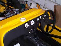
Did a few little bits this week like filing down the nuts on the carb linkage to give me a few mm more clearance from the
bonnet (yes, it's that close). Also sprayed the inside of the passenger footwell black, so you can't make out the dodgy panel
work down there. Much better..... Got the speedo working at last - wasn't my fault after all. I followed the instructions
perfectly, unfortunately they were wrong. It wasn't until I got to speak to the man at the factory with the circuit diagrams
that we found this out though. Basically (dull bit coming up for those not facing this problem) the red wire is connected to
the ignition switched 12v supply to provide a pull-up on the signal from the hall-effect sender. This is normally required as
most (or at least their) sender is open drain, so the output switches between ground and open circuit. Adding a pull-up gives
a 0v/12v pulsing signal. However, the Ford sender is powered and switches between 0v/12v already so the pull-up was causing
the voltages to be such that the speedo wasn't detecting the pulses. Simple answer: chop the red wire.... (just like in all
good action films). And lo, it works, the needle moves when you spin the rear wheels.
The sender is an 8-pole hall effect one, so you get 8 pulses per revolution. The formula for working out the calibration
number is: R x D x P where R is the number of revs/mile with your wheels, D is the diff ratio and P is the number of pulses per
rev from your sender. My tyres are 205/45-16, which give an approx rolling circumference (unloaded circumference x 0.97 approx)
of 1.8m. 1609.344m in a mile gives 893 revs per mile of the rear tyres. My diff ratio is 3.78 and 8 pulses per sender revolution
gives 27027 pulses per mile.
Week 61
Decided on where to put the side repeaters - just inside the footwells near the top. Most people put them in the engine bay,
but that makes wiring slightly harder and besides, I've got cooling hoses and wiring in the way there. Made a pilot hole then
a 22mm hole saw to make the hole in the tub for the repeaters (which are little round Hella ones from some unknown car). After
tidying up the hole they popped in and I chopped the wires to the right length. They're earthed by screwing a ring terminal
onto the chassis, and I've got the supply lead running to the back of the indicator warning lamps (easiest to tag onto). The
lamps themselves are held onto the tub using Sikaflex. The wiring's for the passenger side one's run around underneath the
battery tray, tacked into corners where I couldn't easily fix things, using a blob of Sikaflex - works great and it's really
easy.... ;-)
Also, finally got round to fixing the drivers side trailing arm bolt cover (about 9 months after doing the passenger side one).
Sprayed the drivers footwell panel black on the inside.
I've been planning the nose and bonnet fitting. I'm going to hinge the nose at the bottom (was always my plan) to avoid the
bending and cracking that you get otherwise. It's a bit awkward to get a hinge onto, but I reckon it'll work. I've got a pair
of 25mm wide 40mm long hinges which should give me plenty to fix onto. At the rear of the nose up top I'm going to make a pair
of brackets to support the nose, rather than resting it on the headlamp stays as suggested by Tiger. All this involves is a bit
of bent metal and a Dzus fastener on each side. This way it'll hold the front of the bonnet in position too which will help a
bit with the underbonnet clearances I seem to have slight problems with.
Only 6 weeks to go - I'd best get a move on.....
 A pretty productive week, all-in-all. Fitted all the interior carpet and trim (temporarily). The side panels were screwed
into the chassis and tub. The rear carpet had a horseshoe shape cut out to pass over the transmission tunnel. The handbrake and
gear stick gaitors were chopped a bit to allow free movement, then fixed down using double-sided sticky tape to hold, and narrow
offcuts of 1mm steel sheet screwed in to give a bit of security. After all that I bolted down the scuttle, using a few layers of
household draught excluder underneath the front edge of the scuttle to ensure a (mostly) watertight seal between battery tray
and scuttle. Also put a single piece under each edge of the scuttle where it meets the tub to provide a bit of sealing. As the
sikaflex had cured I connected the repeaters up and they work fine. Used some more of the stuff to stick down the rubber trim
which goes over the scuttle where the bonnet rests.
A pretty productive week, all-in-all. Fitted all the interior carpet and trim (temporarily). The side panels were screwed
into the chassis and tub. The rear carpet had a horseshoe shape cut out to pass over the transmission tunnel. The handbrake and
gear stick gaitors were chopped a bit to allow free movement, then fixed down using double-sided sticky tape to hold, and narrow
offcuts of 1mm steel sheet screwed in to give a bit of security. After all that I bolted down the scuttle, using a few layers of
household draught excluder underneath the front edge of the scuttle to ensure a (mostly) watertight seal between battery tray
and scuttle. Also put a single piece under each edge of the scuttle where it meets the tub to provide a bit of sealing. As the
sikaflex had cured I connected the repeaters up and they work fine. Used some more of the stuff to stick down the rubber trim
which goes over the scuttle where the bonnet rests.
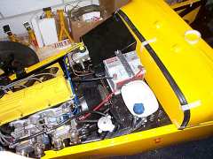 The battery's clamped down using two M6 threaded rods which are sealed into a pair of rivnuts, one either side of the battery
on the battery tray. An offcut of 5mm thick aluminium is then held down on top of the battery clamping it in place. While at
the scrapyard on Saturday (looking for bits for another car) I got hold of a pair of pedal rubbers which fit over the rather
large clutch and brake pedals. They're off the large brake pedal from an automatic Vauxhall Carlton (or, rather, from two
Vauxhall Carltons), and are now held on with a squirt of contact adhesive. Once that was done I drilled the pedal pivot rod and
the tube it sits in and put a split pin in to hold it all together.
The battery's clamped down using two M6 threaded rods which are sealed into a pair of rivnuts, one either side of the battery
on the battery tray. An offcut of 5mm thick aluminium is then held down on top of the battery clamping it in place. While at
the scrapyard on Saturday (looking for bits for another car) I got hold of a pair of pedal rubbers which fit over the rather
large clutch and brake pedals. They're off the large brake pedal from an automatic Vauxhall Carlton (or, rather, from two
Vauxhall Carltons), and are now held on with a squirt of contact adhesive. Once that was done I drilled the pedal pivot rod and
the tube it sits in and put a split pin in to hold it all together.
Week 62
Another pretty good week. After picking up a snail-shell type horn off a late Vectra last week, fitted it just behind the rad
on the drivers side. I made a solid bracket to hold it down, but on trying it out the horn emitted a dull f*rting noise. Oh.
However, as the mounting nut came loose (it was only done up finger tight) the noise got better and better. Okay then, so it
turns out it's got to be fitted to a rattly vibrating bracket or it doesn't work. Clever....... Fitted the bottom of the nose
using a pair of hinges between the inside of the nose and the bottom of the chassis crossmember by the tabs on the chassis. I'm
not using the tabs with captive nuts at all - I put a couple of rivnuts into the crossmember to hold it all on, with rivets between
the nose and hinges. Works well, but won't be any use once the lights are on - the nose is wider than the gap between the
headlamps so it won't be able to hinge forward much at all.
Once that was done, the bonnet was sat on top, and lined up along the scuttle. I marked the positions for the rivets to hold
the rear catches onto the tub/chassis, drilled and rivetted them on. Then, with the help of my beautiful assistant to hold the
bonnet in place, I marked the hole positions for the other half of the catches on the bonnet. After taking it off again, I moved
the holes up 1mm or so to give a bit more tension on the bonnet, drilled and rivetted the hooks on. And the bonnet is now held in
place (at the back at least - the spring clips at the front end are going to take a little more thought, and the nose is going to
have to get some support at the back end to give me a little more clearance over the throttle linkage.
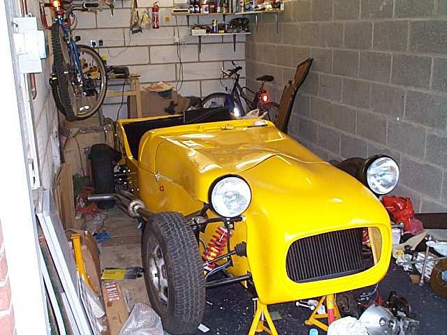
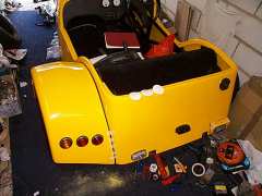
 Oh yes, minor thing - cut the spare wheel carrier off the chassis ;-) Started off with the jigsaw, but it soon became clear the
blades I had weren't long enough, so I ended up using a junior hacksaw (Hint: it's easier to get in before you fix the tub down,
kids....) Wasn't too hard, and 5 minutes each side saw the thing fairly cleanly off. I tidied up with a file, and now have a
very neat and clean look at the back - except for the notches which Tiger had pre-cut in the GRP. I'm not worried about this at
all, thanks to a brilliant idea from Antony Moxey (another Six builder), covering the cutouts with a plastic numberplate surround.
I picked up a nice looking matt black one from Halfords for less than 8 quid, which is the exact size I needed. I'm happy now. ;-)
The picture shows the surround loosely stuck on - it'll be better when it's finally fixed. That black bit on the floor is the
carrier....
Oh yes, minor thing - cut the spare wheel carrier off the chassis ;-) Started off with the jigsaw, but it soon became clear the
blades I had weren't long enough, so I ended up using a junior hacksaw (Hint: it's easier to get in before you fix the tub down,
kids....) Wasn't too hard, and 5 minutes each side saw the thing fairly cleanly off. I tidied up with a file, and now have a
very neat and clean look at the back - except for the notches which Tiger had pre-cut in the GRP. I'm not worried about this at
all, thanks to a brilliant idea from Antony Moxey (another Six builder), covering the cutouts with a plastic numberplate surround.
I picked up a nice looking matt black one from Halfords for less than 8 quid, which is the exact size I needed. I'm happy now. ;-)
The picture shows the surround loosely stuck on - it'll be better when it's finally fixed. That black bit on the floor is the
carrier....
Week 63
Went round to see Neil Wain's progress on the Zetec installation. It's getting there pretty quickly now, he's got most of the
bits now, and the engine and box are connected and sitting in place. The biggest thing left is getting some engine mounts fabricated
to hold it in the right spot. We tried my nosecone on his car to see if it would help a little with under bonnet clearance, which
it did, to the tune of 1 - 1.5" !!! Looks like the reprofiled nose and bonnet give a bit more room. I suspect he'll be getting a
new nose and bonnet now, as this gives him plenty of clearance under the bonnet (except for the injector wiring) and around 4" of
sump clearance.
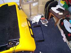
As you might have spotted in the picture above, the front nearside wheel is off, along with the hub and upright. I'm having a
friendly garage replace the wheel bearing, as it's become more and more dodgy over time. Should be back by the weekend.
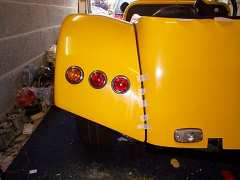
Well, the weekend came and it's not back yet. Ah well, got other things to do anyway. Been sorting out the lights at the back
end, which has taken some time. Deciding on positions (SVA compliant, of course - summary, all lights except fog and reverse must be
at least 350mm off the ground - fog and reverse 250mm. Tail, indicator and brake lights <400mm from the outer edge of the car,
fog lamp must be on right hand side of car or have one on either side). Chopped all the wiring back to the right length, drilled
mounting holes in body for number plate lamp and fog lamp, with reverse in the opposite position from the fog lamp. The face of the
fog lamp must be perpendicular to the ground (newish SVA regulation) so I've used the Tiger rear combination lamp mounting block
which is just right for the job (as I'm not using the standard Tiger lights I don't need them on the wings). I suspect it might fall
off after SVA though..... ;-) I used some rather handy woven sheathing to protect the wiring where it goes through holes in the tub,
it's designed for just such a job, but I hope the inspector agrees.
Decided where I wanted the lights on the wings, and used a 35mm hole saw to drill through. I was slightly concerned that there
may be problems with clearance between the wiring and the tyre, but once they were sat in place it became clear there was actually
at least 2" behind the lights. They were screwed into place and the wires soldered onto the light terminals. Just after doing this
I realised I wouldn't be able to get the wings off again now. Ah well, may as well bolt them down properly then with the trim in
place. All the lights work (it'll be good to have a reverse light - they haven't worked on my last couple of cars!!!) and it's
good to have enough indicator lamps to check the flasher unit properly. I swapped the tail lamp bulb from a 21W to a 10W bulb, as
I think that's roughly what's needed - 21W is bright enough to be a fog lamp!
Almost down to 3 weeks to SVA.....
20 days left...
Discovered tail lights need to be 5W. Tonight was attempting to make a pair of brackets to support the nose near the back
above the top chassis rail. Some funny angles involved, so I ended up reliving early school maths lessons trying to work out
the angles, lengths etc. The nose is going to be fixed to the brackets using Dzus fasteners, which are flat-bladed screw headed
fasteners which clip onto a spring on the rear of the panel. This gives them considerable strength and pulls the two panels
together firmly. They're only a few quid from just about any motorsport bits place. A few weeks ago, after getting a couple,
I figured out what size and position holes were required to mount the spring and fastener - the lower panel (bracket in this
case) needs a 10mm hole for the fastener to go through, and two 3.2mm holes to rivet the spring in behind, each 12.5mm from the
centre of the 10mm hole. The fastener itself uses a 19mm hole and another pair of 3.2mm holes to secure the body, but I can't
remember the position of them. Anyway, the brackets are made, and held to the chassis with M6 rivnuts. All the remains is to
decide on the final nose/bonnet position (hopefully to give me enough clearance over the carb linkage - which I don't have at the
minute) and then I'll drill the holes for the fasteners and that'll be it. I'll take some pics tonight (if I get out there after
lending Neil my nose and bonnet!).
Remaining tasks:
- finish nose fixings and spring clips on bonnet
- driver's side rear wing & lights
- cycle wings
- front indicators and headlights
- interior finishing (carpet & seats)
- tuning
- refitting wheel bearing carrier and setting up front suspension
- mirrors
- holes in bonnet for air intake
- go over every bolt on the car and make sure they're tight and through nylocs.
- add the "SVA kit"....
- arranging insurance
- sorting registration stuff out (forms & inspection) - yes, I know I've left it late, but I had things to do.....
Last Updated 01Aug01
© Andy McMinn